
LOD 100 to LOD 500 MEP Explained for Australian MEP Projects
coordination, builder’s work approvals, fabrication, and handover. It also clarifies which party owns each stage of model development—consultant, head contractor, or trade subcontractor—so that the work can be priced, scheduled, and accepted objectively. This pillar guide explains what LOD means in BIM for MEP, the difference between Level of Detail and Level of Development, how LOD aligns to ISO 19650-style information management, and what each LOD level should contain in Revit MEP for Australian projects.
What LOD Means in BIM for MEP Projects
LOD is the Level of Development. It defines how reliable a model element is at a given project stage for a defined use case. Reliability includes geometric certainty (size, level, and position) and information certainty (parameters, tags, and asset fields).
For MEP services, LOD is particularly important because the installation space is limited, service routes are interdependent, and the construction
sequence is trade-driven. A model that is developed too early wastes commercial effort. A model that is developed too late transfers risk to site.
The correct LOD is the point where the model becomes fit-for-purpose for the next decision.
- Design validation: service zones, risers, plantroom feasibility.
- Coordination: clash detection and interface resolution across trades.
- Construction: penetrations, supports, shop drawings, and fabrication spooling.
- Handover: as-built verification and structured asset data for operations.
Difference Between Level of Detail and Level of Development
The Australian market still confuses “Level of Detail” with “Level of Development”. This causes misaligned expectations and unpriced scope.
Level of Detail
Level of Detail is about graphical richness. It describes how visually complex an element appears in the model. Visual richness does not guarantee accuracy, coordination readiness, or constructability.
Level of Development
Level of Development is about reliability. It indicates whether geometry and information can be depended upon for a defined purpose. A simple representation can be fully reliable (LOD 300 coordination intent) while a detailed family can still be unreliable if it has not been validated.
BIM LOD Standards Australia: NCC and ISO 19650 LOD Alignment
Australian projects typically define LOD requirements through the BIM Execution Plan (BEP), the model responsibility matrix, and the information delivery schedule. While ISO 19650 does not prescribe specific LOD numbers, its information management approach supports clear definition of model status, exchange gates, and accountability.
LOD expectations should be aligned to project controls that Australian builders and developers already use: documentation stages, hold points, penetration approval workflows, and trade coordination gates. It should also be consistent with NCC-driven compliance documentation and commissioning requirements where those are contractually required.
A practical alignment approach is to define LOD at element-category level: plant, distribution, terminations, penetrations, supports, and builder’s work. Then link each category to acceptance criteria and responsibility (consultant vs contractor vs specialist trade).
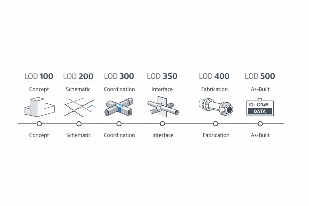
LOD 100 (Concept Design Phase)
Definition
LOD 100 communicates conceptual intent and spatial allowances. Elements are symbolic and indicative only.
Typical MEP model content
- Plant allowances shown as blocks for major equipment.
- Indicative service zones and riser locations.
- High-level routes showing intent, without offsets or coordination certainty.
Geometry accuracy
Low. Not suitable for clash detection, penetrations, or construction decisions.
Data attributes
- System classification (HVAC, electrical, hydraulic, fire).
- Early assumptions (approximate loads/capacity placeholders).
Project stage
Concept / feasibility.
Responsibility
Consultant-led.
Australian example
During feasibility for a healthcare expansion, plantrooms are volumetrically tested to confirm floor-to-floor heights and acoustic plant separations. Services are not routed; the objective is spatial viability.
LOD 200 (Schematic Coordination)
Definition
LOD 200 introduces approximate geometry and routing logic. The model communicates intended distribution paths and primary equipment positions.
Typical MEP model content
- Schematic duct, pipe, and containment routing with indicative sizes.
- Riser corridors and major shaft allocations.
- Preliminary equipment placement and access intent.
Geometry accuracy
Medium-low. Useful for early spatial coordination but not for trade-set installation.
Data attributes
- Preliminary schedules and key performance placeholders.
- Early tagging framework (often incomplete at this stage).
Project stage
Schematic design / early design development.
Responsibility
Consultant-led, with possible ECI input.
Australian example
In a multi-storey office building, LOD 200 validates riser capacity against structure and architecture before ceiling heights are locked and major builder’s work is committed.
LOD 300 (Detailed Design Coordination)
Definition

LOD 300 defines coordinated design intent. Elements are modelled to accurate size, level, and location for reliable coordination. This is the baseline for LOD 300 MEP modelling used in clash detection.
Typical MEP model content
- Accurate ductwork, pipework, and containment sizes and elevations.
- Equipment positioned to support spatial validation and access intent.
- Penetration requirements defined for coordination workflows.
Geometry accuracy
High for coordination. Fit for clash detection and design coordination sign-off gates.
Data attributes
- Consistent tagging, system identification, and parameter standards.
- Specification references and key performance parameters where required.
Project stage
Detailed design / construction documentation.
Responsibility
Typically consultant-led, unless transferred earlier under ECI arrangements.
Australian example
On a tertiary education building, LOD 300 models are federated for coordination gates before issue-for-tender, reducing post-award redesign and variation exposure.
LOD 350 (Interface Coordination Between Trades)
Definition
LOD 350 captures trade interfaces and constructability conditions. It adds coordination of penetrations, supports (where required), and connection intent
to reduce installation risk.
Typical MEP model content
- Coordinated builder’s work openings and penetration sets.
- Interface allowances for supports and hangers (as defined in the BEP).
- Connection interfaces where spatial or sequencing risk exists.
- Access and maintenance zones validated against architecture.
Geometry accuracy
High. Suitable for penetration approvals and construction-facing coordination gates.
Data attributes
- Penetration IDs, status tracking, and approval workflows (project dependent).
- Installation intent parameters (support type intent where applicable).
Project stage
Pre-construction coordination.
Responsibility
Typically contractor-led trade coordination, with consultant verification where contracted.
Australian example
On a congested CBD tower, LOD 350 enables early penetration control across post-tension slabs and transfer beams, reducing late drilling
and re-certification risk.
LOD 400 (Fabrication & Shop Drawing Level)
Definition

LOD 400 is fabrication-ready. It supports production of LOD 400 shop drawings, spools, and installation packages. Geometry and data are developed to match trade fabrication standards and construction methods.
Typical MEP model content
- Fabrication-grade duct segments and controlled fittings.
- Pipe spooling with assembly logic and prefabrication constraints.
- Containment fittings, bracket interfaces, and construction-ready connections.
- Outputs aligned to shop drawing and installation workflows.
Geometry accuracy
Very high. Suitable for fabrication and installation.
Data attributes
- Fabrication IDs, assembly references, and part coding where required.
- Parameters supporting procurement and QA tracking (project dependent).
Project stage
Construction / fabrication.
Responsibility
Trade subcontractors (mechanical, electrical, hydraulic, fire), governed by scope and deliverables.
Australian example
On a major transport project, mechanical fabrication modelling drives spooling and installation packages for corridor services, reducing drafting
duplication and improving installation certainty.
LOD 500 (As-Built & Asset Management Model)
Definition

LOD 500 represents verified installed conditions. It supports handover and asset management where required. This is the core outcome of LOD 500 as-built BIM.
Typical MEP model content
- Verified installed locations of plant, distribution, and key interfaces.
- Final routing positions reflecting approved site changes.
- Asset tagging aligned to the client’s asset register and naming rules.
- Commissioning and warranty fields where contractually required.
Geometry accuracy
Verified against installed conditions, using redlines and field verification. Where specified, validation may include survey or scan-based checks.
Data attributes
- Asset IDs, serial numbers, model numbers, warranty periods.
- Maintenance data fields aligned to the handover specification.
- COBie or client-defined asset schema where required.
Project stage
Handover / close-out / operations transition.
Responsibility
Typically contractor-led, coordinated with builder and client handover requirements.
Australian example
On a government facility, the LOD 500 model is delivered with structured asset data aligned to the client’s FM platform, supporting lifecycle maintenance planning and future refurbishments.
LOD 100 to LOD 500 MEP: Comparison Table (MEP LOD Levels Australia)
| LOD | Reliability | Typical use | Data expectation | Responsibility | Stage |
|---|---|---|---|---|---|
| 100 | Conceptual | Service zones, feasibility | Minimal | Consultant | Concept |
| 200 | Approximate | Schematic routing intent | Preliminary | Consultant | Schematic |
| 300 | Coordination-ready | Clash detection and design coordination | Moderate | Consultant / ECI | Detailed design |
| 350 | Interface-resolved | Penetrations and constructability coordination | Installation-oriented | Contractor | Pre-construction |
| 400 | Fabrication-ready | Shop drawings, spooling, installation packages | Fabrication data | Trade subcontractor | Construction |
| 500 | Verified installed | As-built record and asset handover | Asset schema | Contractor / FM | Handover |
Common LOD Misunderstandings
LOD numbers are not “quality grades”
LOD describes reliability and intended use. A higher number is not automatically “better” if it is not required for the stage.
LOD 300 is not fabrication
LOD 300 supports coordination. LOD 400 supports production. Confusing these creates unpriced scope and late rework.
LOD must be defined by element category
Plantrooms, risers, and high-risk corridors often need earlier development than typical branch distribution. A single blanket LOD target is rarely workable.
LOD 500 requires verification
LOD 500 is not a design model updated with “as-built notes”. It requires installed verification and agreed asset data fields.
Risk of Over-Modelling or Under-Modelling
Over-modelling
- Unpriced modelling effort and scope disputes.
- Slow coordination due to large files and heavy federations.
- False confidence if detail increases without validation.
Under-modelling
- Late clashes and site rework.
- Uncontrolled penetrations and builder’s work variations.
- Procurement and sequencing errors caused by uncertain routing.
- Handover failures when asset requirements are missed.
The control measure is governance: define LOD acceptance criteria in the BEP, lock exchange gates, and audit model compliance at each issue.
Contractual Implications for BIM Documentation Requirements Australia
LOD must be contractable. If LOD expectations are not tied to scopes of work and BEP deliverables, the project inherits uncertainty. That uncertainty appears later as variations, disputes, and programme claims.
- Define consultant LOD deliverables separately from contractor trade LOD deliverables.
- Link payment milestones to accepted model exchanges with objective checks.
- Specify what is excluded (fabrication, hangers, supports) if it is not in scope.
- Include model status and approval workflows aligned to ISO 19650-style exchanges.
Real-World Example: LOD Progression on an Australian Commercial Project
A controlled LOD progression reduces risk when it is treated as a series of acceptance gates.
The following sequence reflects what typically works on commercial projects.
- LOD 100: confirm service zones, riser capacity, and plant allowances.
- LOD 200: validate primary routes with structure and architecture before documentation is locked.
- LOD 300: complete clash detection and design coordination sign-off.
- LOD 350: control penetrations and high-risk interfaces; coordinate constructability constraints.
- LOD 400: produce shop drawings, spools, and installation packages from the trade model.
- LOD 500: verify installed conditions and deliver structured asset data for handover.
This progression only holds when responsibilities are defined and the BEP sets acceptance criteria for geometry, parameters,
naming conventions, and model status at each exchange.
FAQ: LOD 100 to LOD 500 MEP
What is the difference between LOD 300 and LOD 350 for MEP?
LOD 300 is coordination-ready design intent. LOD 350 extends coordination into interfaces: penetrations, constructability constraints,
and trade interaction zones that reduce installation risk.
Is LOD 400 shop drawings modelling always required?
No. LOD 400 shop drawings modelling is required when the contract calls for fabrication-driven documentation, prefabrication,
or model-based installation packages. It should be clearly scoped and priced by the trade.
When should LOD 500 as-built BIM be specified?
Specify LOD 500 as-built BIM when the client requires structured digital handover for operations, future refurbishments,
compliance traceability, or FM integration. Define the required asset schema and verification method up front.
How does ISO 19650 LOD affect Australian projects?
ISO 19650 LOD influences how you control information exchanges, model status, approvals, naming conventions, and responsibilities.
LOD requirements should be embedded into the BEP and information delivery schedule so they are enforceable.
Who owns the Revit MEP LOD model at each stage?
Typically, consultants own LOD 100 to 300. Contractors and specialist trades typically own LOD 350 to 400.
LOD 500 is usually contractor-led for handover, aligned to the client’s asset requirements.
What are the most common BIM documentation requirements Australia teams miss?
The most common gaps are unclear LOD acceptance criteria, incomplete responsibility matrices, inconsistent parameter standards,
and undefined penetration governance. These gaps create scope drift and coordination failures.